Since 1974, Bang & Olufsen has had both audio and video products that could be controlled remotely. The first remote controls used ultrasound, with a small speaker placed at the tip of the remote control, and a detector in the devices themselves. The frequencies used were outside the range that humans can hear, but the tones could easily be heard by cats and dogs who were not always happy when the devices were remotely controlled. The range was quite limited, but the television screens were also somewhat smaller than is the norm today. It was mainly the most expensive and advanced radios and televisions that could be remotely controlled.
With the first microprocessors in products, it became possible to use infrared light instead of ultrasound for remote control. For audio devices (the Beocenter 7000 and Beomaster 8000 being the first), a Texas Instruments IC was used that could decode a keyboard and emit an 8-bit infrared code. The first bit was always 1, with sending of IR, to get a well-defined start. The last bit was hard-coded as either 0 or 1. The value 0 was used for the Beocenter, and the value 1 for the other devices. With the crystal selected, each bit was 3.12 msec long, and the code was transmitted four times, with an 8-bit long pause between each 8-bit code transmission, and repeated for as long as the key was held down.
The microprocessor had to detect two identical code transmissions in succession before the code was accepted and the functions activated. Codes such as volume control had to be detected as long as the keys were held and the codes sent from the remote control. As the IR detector was running with an automatic gain control (AGC), the first transmission was not always decoded correctly. There was also a disadvantage to using a 0 as the last bit as in the Beocenter codes, as noise from other infrared light sources, such as sunlight, could be seen as valid code transmissions. For example, the data code 0 would be sent as a single IR bit of 3.12 ms, followed by 7 bit length pause, followed by 8 bit length pause, before the next start bit was sent. I.e. 3.12 ms transmission followed by almost 47 msec pause.
Thus only 6 data bits, or 64 different codes, were available. This was sufficient for the first devices, but only because video used a completely different format. The same codes were transmitted on the link between the Beomaster 8000 and the Beocord and Beogram 8000. Because there was not the same noise on a hard-wired link as on an infrared transmission, the codes were only sent twice. Since the link was a two-way communication, a device had to ensure that there was no activity on the line before transmission was started.
Later, this system was extended to send infrared codes in both directions to and from the Beocenter 7700. Here a short pulse was sent from the remote control before sending codes to adjust the AGC for the upcoming data codes. The Beocenter 7700 only sent a return code immediately after receiving a code from the control panel.

Simultaneously with the development of IR remote control for audio products, a completely different IR remote control was developed for video products, i.e. televisions and video recorders. This was used from 1981, first in the Beovision 8800, and has a code format where for each bit a short pulse of about 150 microseconds is emitted followed by a pause whose length gives a total bit time of 5.12 msec for a 0 and 7.16 msec for a 1 bit. The start bit is always a 0 bit, and it is followed by 6 data bits and no stop bit, with a longer pause before the code is repeated. The time for a code transmission is thus dependent on the code itself. Because of the very short pulse at the start of each bit, the power consumption is very low, but this meant that the pulse either had to be extended internally in the receiver, or it had to be received in an interrupt for the slow microprocessors to be sure of catching a bit start pulse.

The Philips VCRs used by B&O used internally a completely different format which Philips had developed for infrared remote control of their own sets, and which was also used by other manufacturers. The system, called RC5, is still used for remote control, but with some adaptations over the years. The bit time was 1.778 msec, and a 1-bit consisted of an IR signal in the first half of the bit time with a pause in the second half, and a 0 bit was a pause in the first half and IR signal in the second half. Thus, there could be at most a single bit time pause in the transmission. The code format where there is always a switch in the middle of the bit time is called Manchester coding.
The first two bits were start bits (always 11) partly intended for AGC tuning, followed by a control bit which changed every time a key was pressed, a 5-bit address identifying the type of receiver (TV, radio, gramophone, etc.), and finally a 6-bit command code. The total time for a code was thus almost 25 msec, and these were repeated for every 114 msec or as long as a key was held down, but otherwise sent only once. Philips later found that 64 command codes were not sufficient, and changed the meaning of the second start bit. The value 1 indicates original format, the value 0 indicates an additional set of 64 codes.
The advantage of including a receiver type in the code was of course that it was not necessary, as it was with B&O’s video codes, that both TV and VCR had to know which of the two was currently selected for control. The purpose of the control bit was to detect whether it was a key that was held down, or a re-press of the same key when the same code was received twice in succession. On B&O video tape recorders with Philips running gear, B&O video remote control codes had to be converted to RC5 codes before being passed to the VCR controller. At least in those devices where B&O did not have direct access to the internal I2C bus that Philips also used.
The Beomaster 5000 with its Master Control Panel which exchanged larger amounts of information used a completely new protocol compared to earlier audio protocols. The bit time was of fixed length and pulses were sent for both 0 bit and 1 bit, but the pulse time was different for 0 and for 1.

For the integration of audio and video remote control, a new protocol was then developed again and a different carrier frequency for the infrared light was used. Egon Bjerre, who was responsible for the electronics of the Beocenter 7000, explains the choice of frequency for the Beolink 1000:
During the 40 years I worked in the development department at B&O, I was involved in the development of remote controls, among other things, until I retired in 2006.
It started with ultrasound, which provided a reasonable solution. However, the range was not very long and as there could be phase-outs and other kinds of reflections, the communication between transmitter and receiver could occasionally fail.
When usable infrared LEDs became available, B&O switched to this solution for transmitting the remote control signal. The carrier frequency was, as for ultrasound, in the range 30-40 kHz. The range was improved and due to the high speed of light, reflections were now an advantage.
I don’t remember the exact process, but at some point I became aware that Philips development people were concerned that the frequency range used might be disturbed in the future. I don’t know if it was low energy bulbs they had in mind.
Philips suggested that the remote control switch to a carrier frequency of 455 kHz. This was the same frequency that many used for AM medium frequency. This was a great advantage, as good bandpass filters were available for this frequency at a favourable price.
I had expected that 455 kHz would become some sort of standard when Philips proposed it, so B&O set about finding solutions for transmitters and receivers.
The circuits in both transmitter and receiver had to be built discretely. That is, with transistors as active components. Especially in the receiver this was critical, as it had to be low noise and at the same time able to cope with a dynamic range of over 100 dB.
The discrete construction meant the receiver took up a little more space and was a little more expensive. This was perhaps the reason why Philips did not switch to 455 kHz itself. I think B&O was the only one on the market with this solution.
The Beolink 1000 was the first remote control to transmit on 455 kHz, and combined with secure encoding, which also had low battery consumption, B&O had the best remote control system in the world.
I expected that when other companies saw what could be achieved with remote control, B&O would soon have a fight on its hands. Dealers and customers alike had no doubt that B&O’s remote control was far superior to what other companies could achieve. For some reason, this did not happen, so B&O was allowed to lead the field. Perhaps it was the small extra cost that made the difference.
The protocol for the new remote control was developed by Søren Borup and Tom Jelsing together with other contributors. As I was not directly involved in the development of this code, Tom has kindly contributed the following description.
Account regarding the principles of Remote Control in B&O products.
Before I tell you a bit about remote control of B&O products, I just want to tell you that I left B&O in 1989 and have not been in contact with B&O development department since, so there are many gaps in my memories. However, after Arne Rohde contacted me and told me about his BeoMikro story, various things have turned up anyway, especially about the last IR code format we developed in 1984/85, where I found some material from the development work in a box in the attic. But first a bit about the earlier remote control concepts at B&O, as best as I remember.
1. Ultrasound
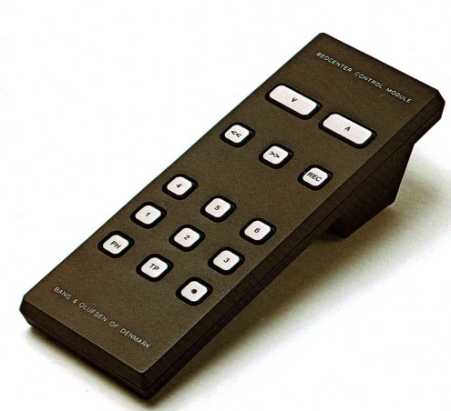
The first principle we used was based on 35 kHz ultrasound as the carrier medium. It worked reasonably well, but ultrasound had the unfortunate property that sound reflected off walls and objects in the room and the sound waves could therefore cancel each other out before they hit the receiver microphone. This was less of a problem on a TV, where it was natural for the user to point the terminal at the device. But B&O were also the first on the market (I think) to introduce remote control of audio products. On the first terminals, the keys were shaped like a u-shaped tab cut out of a thin stainless steel plate. When the user pressed the key, the tab bent down and hit a soft contact spring underneath. There was therefore no tactile feedback. As a result, terminals were regularly returned to dealers with the tab still bent down, because the user had instinctively pressed harder and harder when the device did not respond as expected, nor did it give an initial response!
2. TV remote control
B&O’s development department was divided into several sub-departments including the TV department and the Radio department, where I found myself in the latter. The TV department made its own remote control, which I was not involved in. Only later did we develop a common concept so that TV and Radio could be operated from the same terminal.
3. IR Format 1G and Datalink
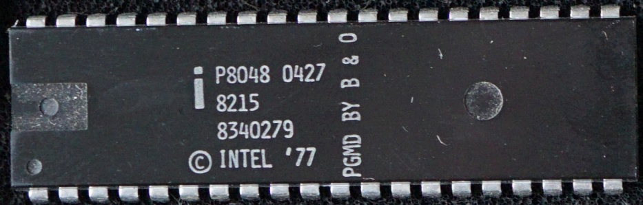
Infrared light (IR) is a more suitable carrier medium for remote control and when dedicated ICs and optoelectronics for the purpose came on the market, we switched to using IR. The first product was BeoMaster 6000 (or was it Beocenter 7000 [it was Beocenter 7000]), where Egon Bjerre was project manager and had designed the IR receiver. In the remote control terminal a dedicated IC from Texas Instruments SN76831 was used.
SN76831 was also used in the remote control terminal for Beomaster 8000, where my task was the design of the microprocessor HW and SW. Depending on which control key was pressed, the SN76831 defined a code of 8 bits, which was sent serially in the form of IR light flashes. The individual bits were amplitude modulated on a 38 kHz carrier wave to distinguish from unwanted IR light/radiance/noise. The bit time was 3.125 msec and the total time for the whole code was thus 25 msec. Bit value 1 thus resulted in a 3.125 msec long 38 kHz burst and bit value 0 in a 3.125 msec gap where nothing was transmitted. The code was sent as long as the user held down a key separated by a longer gap with code value 0, which contributed to a unique start condition. The IR transmitter consisted of one or more IR LEDs that converted the electrical signal into a light signal.
In the IR receiver, the light signal was first filtered in an optical filter (with a large optical bandwidth) before hitting a photodiode connected in series with a 38 kHz oscillating circuit, so that only light modulated with frequencies close to 38 kHz was converted into an electrical signal. The signal was amplified in an amplifier with automatic gain control AGC and converted into a digital pulse train that was sampled by the microprocessor every 1.562 msec and then interpreted and further processed in SW. The AGC control was important to achieve an optimal S/N ratio. The gain was set when a 38 kHz burst (with logic value=1) was present and maintained in the gaps (with logic value=0).
The Beomaster 8000 was part of a High Line product concept that also included the Beocord 8000 and Beogram 8000. All 3 products had microprocessor controllers and we therefore had the idea that the devices could send useful information to each other over an extra pair of wires in the audio cables connecting the devices. This allowed B&O’s philosophy of “At the touch of a button” to be fully realised. In order to reuse the decoding algorithm of the BM 8000, we decided to use the same code format generated by the SN76831, but in digital form without the 38 kHz carrier wave. The information exchange was detailed in a Datalink Protocol and it worked out fine.
4. IR format 2G
This code format was developed for the BM 5000. The new and special thing was that we made 2 way IR communication between the BM 5000 and the associated control panel “Master Control Panel 5000”. I was involved in that, but don’t remember much about it. So here Arne or Søren, who wrote the software for the products, may have to step in. At the same time what we called “Master Control Link” MCL was developed, where the devices could be controlled with a remote terminal from another room equipped with extra speakers.
5. IR format 3G
This format was first used in BeoLink 1000, which was a common terminal for TV and audio products, as well as in Beomaster 5500 and in a simultaneous TV product.
The requirements for the new format were:
1. Larger and variable number of bits, to be future-proof for future system concepts.
2. Greater range meaning greater sensitivity when the terminal was not pointing at the IR receiver.
3. Lowest possible battery consumption in the terminal.
4. Very high and measurable security against IR noise being decoded as a valid signal *)The requirements were successfully met in the following way:
1. Egon Bjerre (I think it was) had discovered that IR LEDs and photodiodes had come on the market that could switch at 455 kHz and that this frequency band was less noisy than the 38 kHz band. At the same time, 455 kHz provided an easy way to increase the selectivity of the IR receiver by using a ceramic filter that was on the market and was used in AM radio medium frequency amplifiers.
2. We had often discussed whether a short and powerful IR pulse train had longer range than the wide pulse trains we had been using. A new engineer Jan Simonsen we had in the department pointed out that the narrower the pulse, the greater the bandwidth needed in the receiver for the pulse to get through, but greater bandwidth meant more noise. The optimum was to adjust the pulse width to the actual bandwidth. The bandwidth of the ceramic filter was 10 kHz and the optimal pulse width corresponding to this was 200 µsec.
3. A pulse of 200 µsec per bit requires less power consumption than a pulse of 3.125 msec that we had been using. When I look back at it now and do a little rough calculation, I get for an 8 bit code: 8*.2 msec = 1.6 msec compared to an average of 4 * 3.125 msec = 12.5 msec with the old format. Therefore, with half the battery consumption, 4 times higher transmission power could be achieved (with 2 IR diodes) or vice versa.
4. The task was now to get the data content represented via 200 µsec pulses and this gave me the idea to use the distance between the pulses to define the bit value. At the same time we decided to use a so-called Bipolar Manchester coding, which brought some additional advantages.
The distance between the 200 µsec pulses was always a whole multiple “N” of 3.125 msec. N=1 meant change from 1 to 0, N=2 meant unchanged bit value, N=3 meant change from 0 to 1, N=5 start value and N=4 stop value. Prior to the start value, 3 pulses were transmitted with the spacing N=1 to set the AGC in the receiver. After detection in the IR receiver, the pulses were extended as a logic signal with period time 3.125 msec and value 1 in 1.562 msec and value 0 in the remaining 1.562 msec. The pulse train was then sampled by the microprocessor for every 0.781 msec.
A sampled 1 value therefore always had to be immediately followed by at least 1 sampled 0 value, otherwise an illegal IR was present which could lead to misinterpretation. In this case, the bit was discarded and the further interpretation in the microprocessor was reset and had to start again. This was in principle a “time domain comb filter”. On a timeline consisting of consecutive 1.5625 msec windows, there could only be IR signal in every second window. If there was also IR signal in the intermediate windows, it was illegal noise.
Thus, in addition to the switch to 455 kHz carrier and a much more selective IR receiver, the new format incorporated the additional security factor that all bits in a code had to be individually cleared for the entire code to be cleared. If one bit of the new code had the same error probability as the whole code in the previous formats, then with a code length of 20 bits it would be 1 million times harder for a false signal to get through.
To get a practical measure of where we were in terms of security against illegal IR signals, Jan Simonsen made a “bit acceptance meter”, consisting of the newly developed IR receiver, a µC with the decoding algorithm in Eprom, and a column of 16 LEDs that turned off depending on how many bits were accepted in a row and where the LED showing the highest number was stuck (like on a VU meter). We then exposed this system to various forms of light radiation with infrared content both briefly and over longer periods. The highest reading we got was probably 6 in a row and since the minimum number of bits in the code was 20, we were confident that the principle was bulletproof.
Søren Borup then wrote a data protocol that defined the content of an IR command. The start value was followed by a header with general info, which was followed by the code of the actual command. The total number of bits in a command was above 20, which provided additional security against misinterpretation and could be sent in a perceived acceptable time. (See more on this in a paper by Søren elsewhere [below]).
*) In the earlier IR formats, there was an extremely minimal probability that an illegal IR signal could be misinterpreted into a valid code, but there had nevertheless been some cases where a device had started up by itself and/or where the volume control had been turned all the way up. It should be borne in mind that B&O had in the order of 100 K IR receivers running in products around the world that were open to IR light 24 hours a day and could initiate a decoding at least 20 times per second (equivalent to 60*10E12 potential decodings per year), so the error rate in relation to this was low, but not low enough to completely prevent errors.
Next chapter: Product development
Some historical documents by Tom Jelsing from the 3G development process:


The protocol document (mostly in English) for 3G IR codes was written by Søren Borup (and Tom Jelsing). It was photographed and then converted to PDF.
A Datalink Protocol document for the Beomaster 8000 1G codes, written in Danish by Tom Jelsing is available in the Danish version of this chapter.
